LSST Camera Lenses Explained: Three Giant Glass Elements
Discover how the LSST camera lenses correct field curvature, why three large glass elements are needed, and the engineering behind them.
11 min read
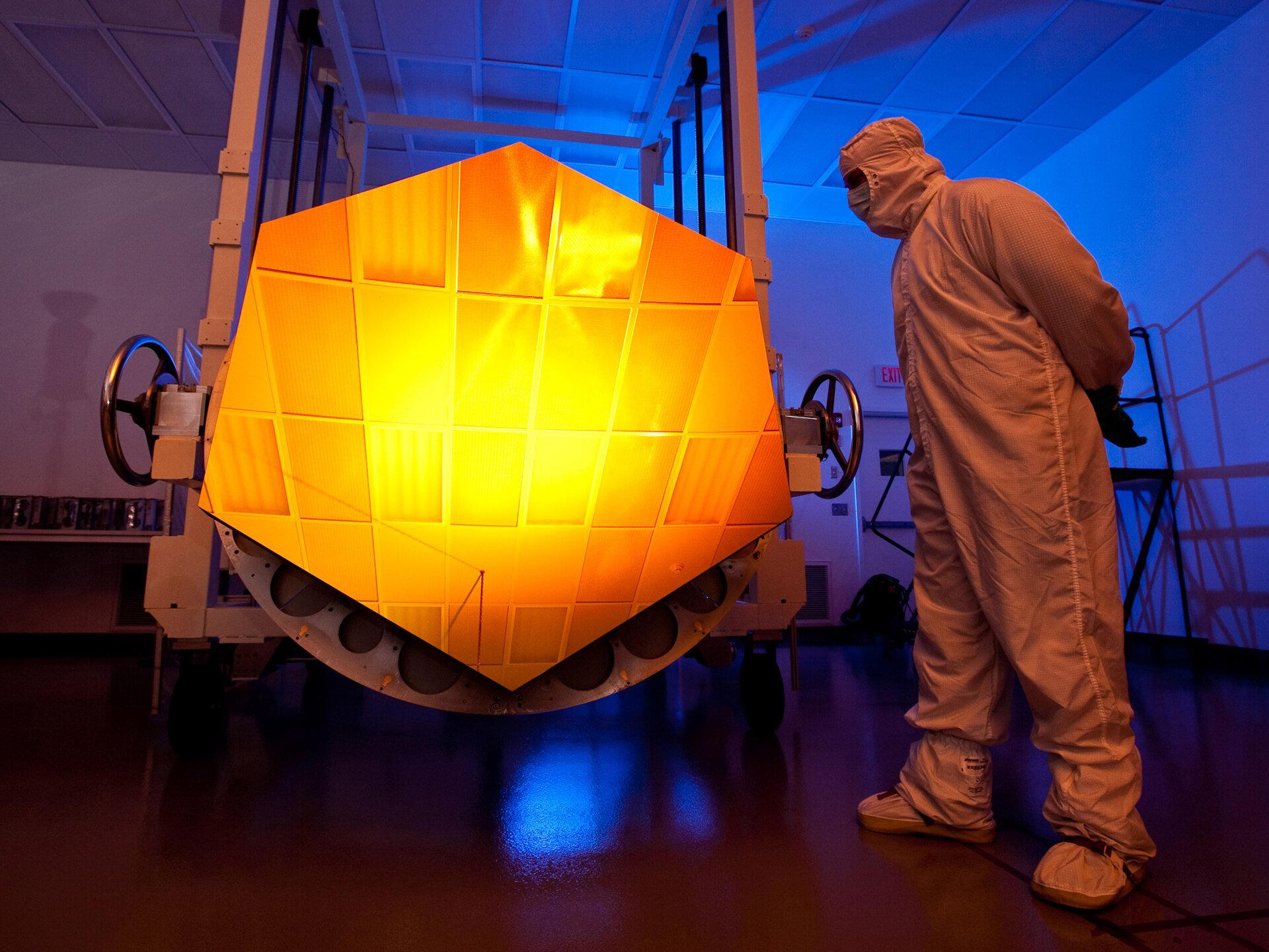
When our team first started digging into the Rubin Observatory’s camera, one question kept coming back to us: how does a single exposure capture a 3.2-gigapixel slice of sky with stars still sharp in the corners? The answer sits in three large pieces of glass. The LSST camera lenses are the reason the image holds together from center to edge, and they are far more demanding to build than their simple appearance suggests. We write this as people who spend our days thinking about optics, not as readers of a press release, and we want to walk through what these elements do, why they are shaped the way they are, and what makes them so hard to make.
What the lenses actually do for the image
The camera uses three large refractive lenses to correct field curvature and flatten the focal plane across a very wide field of view. Without them, the image would look acceptable in the middle and gradually smear toward the edges. The sensor itself is flat, but light coming off a telescope mirror system naturally wants to focus on a curved surface, and that mismatch is the core problem the lenses solve.
The glass bends that light back into shape. Every part of the sensor then sees a crisp image instead of a sharp center surrounded by blur. We have watched teams underestimate this on smaller projects, assuming a mirror system alone would be enough to deliver flat focus. At this scale, it is not, and the lens group is what turns a good design into a usable survey instrument.
Size and material make the job possible, and they also make it hard. Lenses this large are rare in astronomy, and they must hold tight tolerances while sitting in a cold vacuum. A lens that is routine to polish at ten centimeters becomes a very different job at a meter. The physics does not scale gently, and every increase in diameter brings new problems with stress, uniformity, and handling.
Where the lens group sits in the optical train
Light from the sky first strikes the large primary mirror, bounces to the smaller secondary, and then passes through the tertiary before it reaches the camera. The camera is a self-contained unit mounted at the telescope’s focus. The three lenses sit inside it, in front of the filter and the focal plane, and they are the last optical elements the light touches before the sensor.
The mirrors do most of the light gathering, while the lens group handles the final cleanup. Why include refractive glass inside a mirror-based telescope at all? Mirrors reflect light rather than bending it through a medium, so flattening a curved focus across a very wide field becomes hard without added complexity. A small set of carefully shaped glass elements does that job more precisely than trying to correct everything with mirror figure alone.
One way we like to picture it: the mirrors are the engine, and the lenses are the steering that keeps the whole image aligned from edge to edge. The payoff shows up across the full 9.6-square-degree field, roughly 40 times the area of the full Moon. Every part of that field has to be sharp, and the lens group is what stops corner stars from stretching into streaks.
Three elements that step down in size
The three elements are not the same size. They step down from front to back because the light converges as it travels toward the focal plane. The front element is the largest, and each one after it gets smaller. Before quoting exact figures, check the official Rubin Observatory documentation, since specifications get refined over time. The general pattern, though, is consistent and worth understanding.
The first lens catches the widest beam, so it does much of the early bending. Its diameter is the one that makes visitors stop and look closely at the drawings. The middle element refines the focus. It is smaller and easier to handle, but it still has to match its neighbors with very little slack, and a small misalignment here shows up quickly in the final image.
The last piece of glass before the filter works on the outer edges of the field, helping keep the focal plane flat right up to the sensor. Each element plays a distinct role, and removing any one of them would force compromises somewhere else in the design.
Why fused silica and related glasses
Glass choice sounds like a minor detail until you consider that this telescope will run for a decade on a mountain in Chile. The lenses have to tolerate radiation, stay stable as temperatures change, and pass light across a wide band from near-ultraviolet to near-infrared without losing much to absorption. Fused silica and related low-expansion glasses are the usual answer because they handle all three reasonably well.
Large glass pieces bring their own headaches. Refractive index must be very uniform through the whole block, since any variation bends light unevenly. Tiny bubbles or inclusions scatter light and can show up as faint artifacts in the data. Controlling these defects gets harder as the piece grows, which is why the manufacturing process matters as much as the glass recipe itself.
Material also shapes the mechanical design. Glass is heavy and fragile, and it expands and contracts differently from the metal around it. Engineers had to account for weight, for how each lens is held, and for how the assembly behaves inside a cryostat where temperatures drop sharply. A material that looks perfect on paper can still cause trouble if it pulls against its mount.
Making a lens this big
Everything starts with the blank, the rough piece of glass before any shaping. For a lens this size, the blank has to be cast and then annealed, meaning cooled slowly so internal stress does not lock in. Cool it too fast and the glass can crack or hold stress that later distorts the image. Striae, faint streaks of slightly different refractive index, must also be controlled from the start, because polishing cannot remove them.
Grinding and polishing come next. The surfaces are curved, and some are aspheric, so their shape is not a simple sphere. Bringing a large curved surface to the required accuracy is slow, patient work. Teams often use subaperture methods, where a smaller polishing tool works across the surface in small patches. That gives control over the shape without the tool itself becoming the bottleneck.
Checking the work is just as demanding. Interferometric testing compares the surface against a reference wavefront and reveals tiny deviations. If a surface is off by even a fraction of a wavelength, the image suffers. Centration, meaning how well each lens lines up with the optical axis, and thickness tolerances must also stay within tight limits. A lens can be flawless on its own and still hurt the image if it sits slightly off-center.
Coatings that fight reflection across a wide band
Glass reflects some light at every surface. Each reflection costs signal and can produce stray light that blurs or ghosts the image. Anti-reflection coatings reduce this. The challenge is that the camera must work from near-ultraviolet to near-infrared, so a coating tuned for one narrow band leaves the others weaker. Designing one layer stack that performs well across all of it is a real balancing act.
Uniformity is the next problem. A coating slightly thicker in one spot than another changes how light reflects there, and across a very large diameter those small differences add up. Uneven coating can raise stray light, which takes the wrong path and lands where it should not. On a survey telescope hunting for faint objects, stray light is the enemy, and we treat coating uniformity as seriously as any other specification.
Coatings also have to last. The camera lives in cold vacuum, and the coating cannot peel, crack, or drift in its properties over years of use. Durability tests under cryogenic and vacuum conditions are part of the job, not an afterthought.
Alignment, mounting, and cold stability
Placing the lenses is one task. Keeping them in place is another. The lenses must hold position as the camera cools, and the mounts must allow for glass and metal shrinking at different rates. Kinematic mounts are a common answer, constraining each lens at a few well-defined points and letting it move freely in other directions as temperatures change.
A tolerance budget ties all of this together. It links how far a lens can be decentered or tilted to how much the final image degrades. Engineers do not simply aim for perfect alignment. They decide how much error each element can afford, then check that the total stays within what the science requires. That budget is written down before hardware is built, not patched together afterward.
Before integration, each lens group is measured to confirm its alignment against the design. Any deviation is either corrected or accounted for in the budget. Catching a problem at this stage costs far less than discovering it once the camera is bolted to the telescope, and that discipline is what keeps schedules from slipping.
How the lenses are verified
Verification happens at two levels. Individual elements are tested first, using interferometry to check surface figure and transmission measurements to see how the glass and coatings perform. Then the assembled group is tested as a whole, often with MTF measurements. MTF, short for modulation transfer function, describes how well the system preserves fine detail. A high MTF across the field means the image stays sharp from center to edge.
Test data does not simply sit in a report. It feeds back into fabrication. If a batch of glass shows a consistent error pattern, the team adjusts the polishing process or the annealing schedule for the next piece. If the assembled group falls short in the corners, the mounting or tolerance budget gets revised. In our experience, testing drives design improvement, not just a final gate.
For a similar philosophy applied in another setting, our team has written about how optical metrology proves performance before launch. The logic carries over: measure each element, measure the whole, and make sure the data supports the science.
Comparing these lenses with other survey optics
Modern survey and space telescopes share some trends. Refractor elements keep getting larger, glass choices are more demanding, and coatings must cover wider bands with less loss. The LSST camera lenses show all three pushing together, and the lessons carry forward into other large hardware projects.
The environment is where designs diverge. A ground-based survey telescope like Rubin lives on a mountain, deals with weather and daily temperature swings, and can be serviced. A low-Earth-orbit platform faces radiation and vacuum with no chance of a repair visit. The same glass and coating choices may be weighted differently depending on where the telescope lives.
If you want a closer look at how similar trade-offs play out in large hardware, our notes on how large-volume measurement supports spacecraft assembly go into more detail. For teams building their own web presence around technical projects like this, we have also seen good results from working with a thiết kế web partner who understands how to present complex technical content clearly.
Frequently asked questions
How big is each LSST camera lens?
The front lens is the largest, and each lens behind it gets smaller as the light converges. Exact diameters and thicknesses are published by the Rubin Observatory, so check their documentation before quoting specific numbers. The key point is that the group is large enough that making it accurately was a major engineering task.
What material are the lenses made from?
They are made from fused silica and related low-expansion glasses. These handle radiation, temperature changes, and a wide range of wavelengths with low absorption. The glass choice also affects weight, mounting, and thermal behavior inside the cryostat.
Why does the camera need three lenses instead of one?
A single lens cannot correct field curvature across a 9.6-square-degree field without introducing other problems. Three lenses share the work, each handling part of the bending and flattening. That keeps the image sharp from center to edge while limiting aberrations.
What is the hardest part of making these lenses?
Most teams point to the combination of glass quality and surface accuracy at this scale. Controlling bubbles, striae, and internal stress in a large blank is difficult, and shaping and testing a large curved surface to tight tolerances takes a long time. Each problem makes the next one harder.
Do the lenses need special coatings?
Yes. Anti-reflection coatings cut losses and stray light, and they must work from near-ultraviolet to near-infrared. They also have to stay uniform across large diameters and survive cold vacuum over the life of the survey.