Autocollimator Alignment Tutorial: Set Tilt, Check Parallelism
Hướng dẫn autocollimator alignment tutorial từ kinh nghiệm thực chiến: cách set tilt, kiểm tra parallelism và giữ số đo ổn định trên bàn quang học.
8 min read
Every time a mirror or optical window lands on our bench and needs aligning, the first thing we ask is how to measure its angle properly. We have relied on autocollimators for years, and the core method has barely changed. This autocollimator alignment tutorial walks through the steps our team follows, along with two worked examples you can repeat at your own bench and the spots where we tripped up ourselves.
Setting Up the Instrument Before You Measure
Setup decides how far you can trust every reading that follows. Think of the autocollimator as a telescope that both projects and receives light. It sends a collimated beam onto the surface, then reads back whatever reflects.
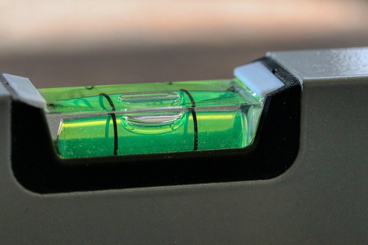
Mount the unit on a rigid holder. We once used a thin aluminum bracket that flexed every time someone walked past the table, and we lost an entire afternoon chasing ghost readings. Level the body against the table with a spirit level or a flat reference plane. Then place a flat reference mirror in position and focus the eyepiece until the crosshair looks sharp.
Before you touch the part under test, note the zero position. It sounds trivial, yet many people skip it and then blame the instrument when the numbers drift. Our own team has been that person more than once, so we now write the zero reading at the top of every log page.
What the Instrument Really Measures
An autocollimator does not measure distance. It measures tiny tilts of a surface, expressed in arc-seconds. One arc-second is an extraordinarily small angle, roughly the width of a human hair seen from several kilometres away, so the number deserves respect.
Why should such a small figure matter? On an optic a few tens of centimetres long, a few arc-seconds of error is enough to shift the beam path through the whole system. Laser users usually notice it first as a drop in output power, or a focus that wanders from one session to the next.
Three error sources come up again and again in our work. Stray room light washes out the signal. Floor vibration from traffic or an air conditioner makes the reading jump. A dusty or fingerprinted reflecting face creates a distorted spot, so you misjudge where the centre really is.
Step by Step: Setting Tilt on a Mirror

This is the most basic task, and it is also where newcomers rush. Place the mirror on a kinematic mount and bring the reflected spot onto the crosshair centre first, before any fine work.
Turn the two tilt screws in small steps, half a turn or less each time. Read the value after every single adjustment. If you turn both screws and then read, you will never know which screw caused which change.
Stop once the residual angle falls within the tolerance on your drawing. If you need better than about 2 arc-seconds, inspect the whole holder rather than keep turning screws. A worn holder will fight you no matter how patiently you turn.
Worked Example: Checking Parallelism of a Window

Suppose you have a flat window with two faces and need to know whether they are parallel. The deviation between the faces is called wedge: the angular tilt between the two faces, where zero means perfectly parallel. In practice you almost never get zero, so the real question becomes whether you sit inside the limit.
Clamp the window in a fixed position. Measure the front face, flip the window, and measure the back face at the same spot. Subtract the two readings to get the wedge, then compare that figure with the value on the drawing.
Write both readings and the calculated wedge in a simple logbook. We once rejected a batch and could not remember why, so every page now records the setup, the readings, and the date. When someone asks later, that page answers the question.
Worked Example: Squaring an Optic to a Mechanical Axis
This problem is different. You want the optical face perpendicular to the mechanical axis of the holder. People often mix the two up, because the mechanical axis does not always coincide with the optical axis of the part.
Start by establishing the holder’s mechanical axis with a dial gauge or a precision rail. Rotate the optic and watch the reflected spot to locate the squareness error. Mark the position of the largest excursion so you can repeat the check later.
- Insert a thin shim if the error is still large.
- Re-seat the part in the holder and recheck.
- Repeat until the error falls below your requirement.
Resist the urge to over-tighten the screws to force it into line. The stress you introduce can distort the optical face later, and then the problem is far harder to find.
Motorised Stages for Repeated Fine Work

If you adjust parts many times a day, a motorised tilt stage saves a lot of effort. The key is choosing a step size smaller than the angular tolerance you need. Otherwise you will oscillate around the target and never quite land on it.
For a broader comparison of alignment stages suited to a laser lab, read our review of Motorized Precision Alignment Stages for Laser Labs. We based our shortlist on repeatability tests in our own setup rather than on brochure figures. Our notes on laser alignment also explain why step size matters so much.
Keeping Readings Stable

A clean reading is not always a correct one. Before you trust a number, let the instrument and the part reach thermal balance. Your hands warm the metal, and metal expands. We usually wait around 15 to 20 minutes after handling a part before we record anything.
Avoid leaning over the table while you read. If you can, place a matte baffle to keep stray light away from the detector. If the value keeps jumping during those first 20 minutes, the table has probably not settled. Check that first, because the instrument is rarely the cause. Our team also keeps notes on vibration isolation for exactly this reason.
Rough Cost Expectations in the Vietnamese Market

The figures below reflect what we see in the Vietnamese market and are only a guide. Prices shift with supplier and timing, so treat them as a starting point rather than a quote.
An autocollimator resolving around 1 arc-second typically runs from about 40 to 90 million VND. A kinematic mount set may cost 3 to 8 million VND, and a calibration service often sits between 2 and 5 million VND per visit. With careful work we usually get repeatability of roughly 1 to 3 arc-seconds.
If your lab only measures a few times a month, do not buy the most expensive unit. Pick one that meets the repeatability you need and put the money into a stable holder. A weak holder ruins every measurement regardless of how good the instrument is, and we learned that the expensive way.
Turning Arc-Seconds into Real Dimensions
Reading the number is one thing. Knowing what it means for your part is another. Convert arc-seconds to radians, then multiply by your working distance to get the linear displacement at the beam end. The conversion is simple, but people skip it all the time.
Take a working distance of 500 mm and an error of 10 arc-seconds. The displacement at the far end comes to roughly 25 micrometres. Whether that ruins the beam depends on your system requirement, so the decision to reject or re-seat the part should rest on this figure rather than on a vague sense that something looks off.
Questions We Hear Most Often
Do I need a digital autocollimator or is an eyepiece unit enough?
An eyepiece version handles rough work well enough. Reading down to arc-second level by eye is hard, though, and tiring after an hour. For repeatable results we recommend a digital unit.
How often should it be calibrated?
With daily use, every 6 to 12 months is a sensible interval in our experience. After any knock or drop, calibrate straight away instead of waiting for the next scheduled date.
Can it measure curved surfaces?
Yes, but the reflected spot moves with curvature, so the readings become harder to interpret. Check against a reference sample before you trust the result.
Why does the reading drift during the first 20 minutes?
Usually it is temperature. Metal and the table need time to balance after you touch them. Wait until things settle before you record the final figure.
Accurate alignment comes from working step by step, recording carefully, and never trusting a single number. Start with a flat reference mirror, then move on to the real part, and the process becomes far more predictable. If you want more background on tables and holders, our posts on optical tables are a good next read. For more on our services, visit tại đây.