Computer Generated Hologram Null Test: A Practical Lab Guide
Learn how a computer generated hologram null test works for aspheric optics, from design inputs and carrier frequency to alignment and reading the final null pattern.
7 min read
When we test an aspheric mirror or lens on the bench, the first question is always the same: does the surface match the design? A computer generated hologram null test answers that directly. A good part produces a nearly flat, almost fringe-free pattern. A flawed part produces something else, and that pattern shows you where the error sits. In our lab, the hologram does most of the heavy lifting, but only when the setup is disciplined from the very beginning.
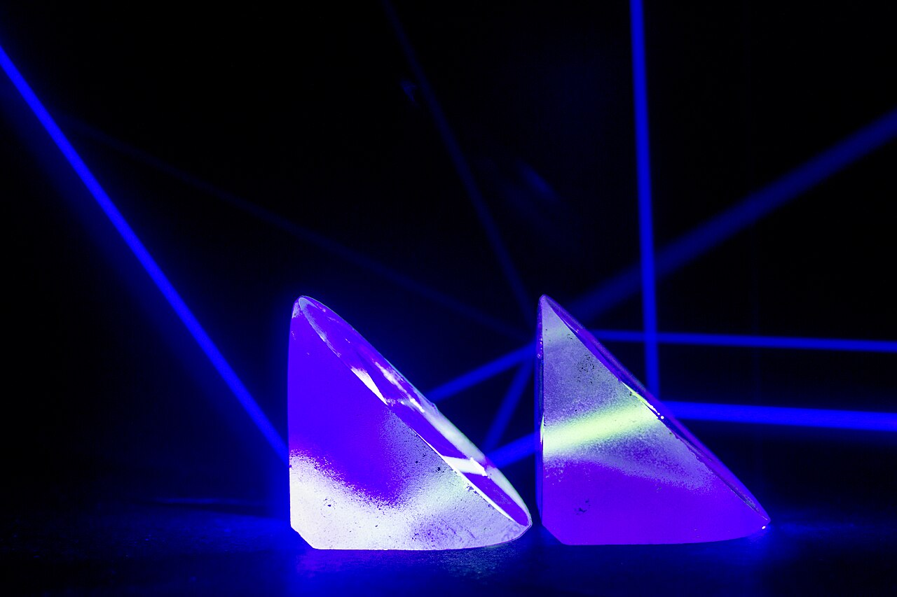
The core idea is simple to state. The hologram is a precisely etched plate that bends the test light into the shape your asphere should have. If the surface matches the design, the two wavefronts cancel and the fringes disappear. We have watched projects go sideways because someone skipped the setup checks and then blamed the part. That mistake is expensive, so we walk through the process in the order we actually follow it on our own benches.
Why a CGH suits asphere testing
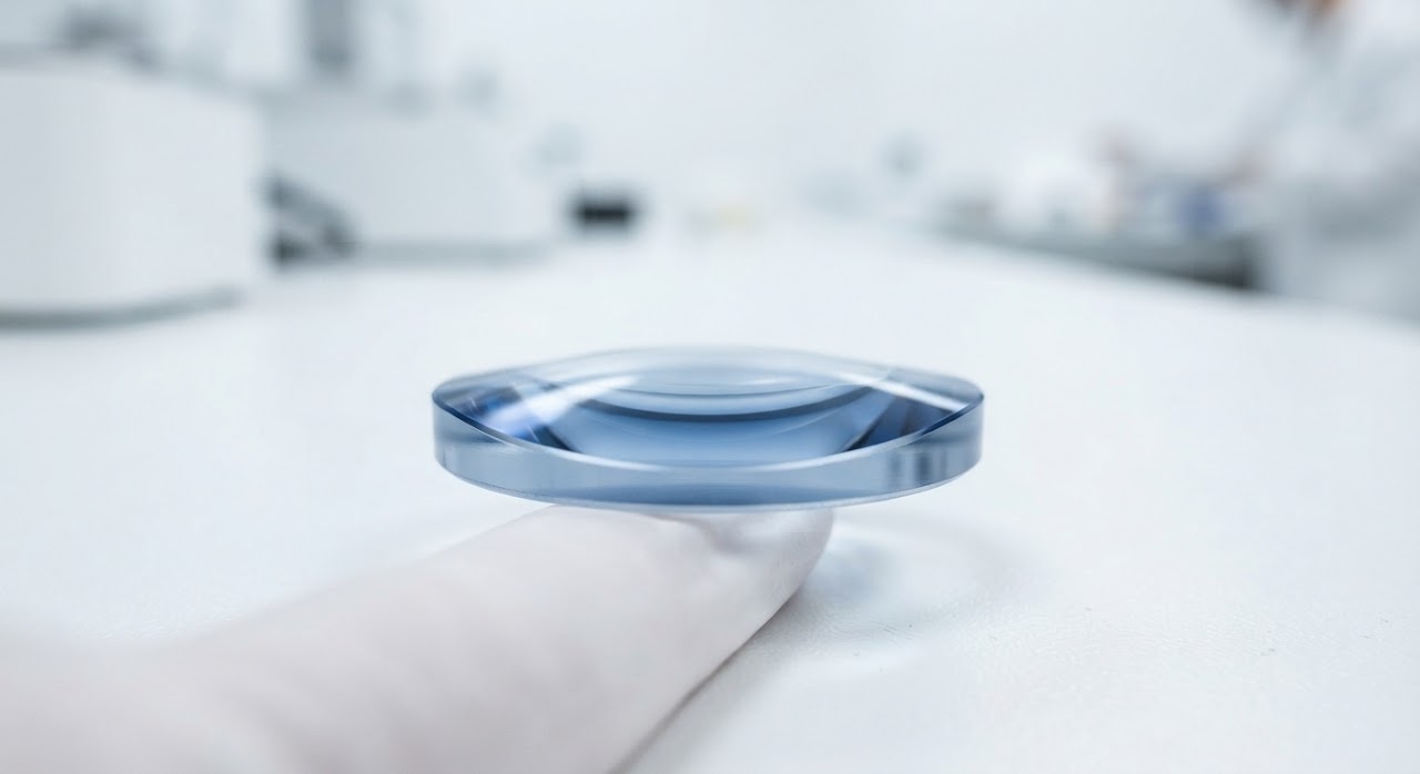
A conventional interferometer struggles once the asphere departs far from a sphere. Without a null optic, the fringes crowd together so tightly that the camera cannot resolve them. Traditional null lenses solve this problem, but they are bulky, costly, and usually locked to a single prescription. A CGH replaces that heavy glass with one etched substrate that you can swap in and out of the beam path.
The trade-off is alignment. The hologram has to sit in exactly the right place, or the null never appears. We treat alignment as the real skill of this method, not the etching itself. A well-made hologram placed poorly will waste an entire afternoon, and we have lost more than one day that way early on.
Gather the design inputs first
Start with the asphere prescription. You need the conic constant, the polynomial coefficients, the vertex radius, the clear aperture, and the sag at the edge. These values describe how far the surface departs from a sphere at every point across the aperture. Without them, the hologram you design will cancel the wrong shape. You will not discover the mistake until the data looks strange, and by then you have already spent the time.
Next, define the test geometry. Record the distance from the CGH to the part, the working wavelength, and the beam diameter of your interferometer. Then set the tolerance budget, usually expressed in waves peak-to-valley. A typical visible-light budget sits at a fraction of a wave, depending on how the part will be used. Write these numbers down now, because you will check against them at the end.
Carrier frequency and hologram design
The design software generates a phase function that reproduces the asphere wavefront in reverse. Verify it with ray tracing before the file leaves for the fab house. Errors caught at this stage cost far less than errors found after fabrication. We have seen a single skipped trace cost weeks of rework.
The carrier frequency is a tilt added to the pattern so the diffracted light separates from the zero order and from stray reflections. Pick a value high enough that your working order stands clear of the rest. Then confirm the carrier stays below the writing resolution of the e-beam or laser writer. A carrier the writer cannot resolve prints as a blurred mess, and you will chase phantom errors for a long time afterward.
- Target carrier frequency: high enough to separate the working order from the zero order
- Writer limit: confirm the fab’s minimum feature size before you finalize the design
- Ray trace result: confirm the residual before fabrication, not after
Alignment marks on the hologram and the part
Add fiducial cross-marks on the CGH substrate and matching reference features on the asphere mounting surface. These marks are your landmarks. Without them, you are guessing where the hologram center sits relative to the part, and a guess can produce a null that looks almost right but is not.
Place the marks in the same coordinate system used in the design file, and keep a written record of their positions. When you return next month to re-test, you want everything back exactly where it was. Teams that skip this step usually spend the first hours of every session re-finding the center, and that time adds up quickly across a production run.
Set up the interferometer and align the hologram
Mount the CGH on a stable stage and bring the test beam to normal incidence at the hologram center. Use the fiducials to center the hologram laterally. Then tilt and decenter until the reference and test beams overlap, and adjust the axial spacing until the diffracted order returns to the interferometer aperture.
This is the slow part, and you should expect several iterations. Each adjustment changes the fringes, so move in small steps and watch the camera between moves. A tilt error shows up as dense straight fringes, while an axial error shows up as a curved bowl or saddle. Small corrections in the right direction get you there faster than large jumps, which tend to overshoot and send you back to the start. For a broader view of how these test benches are planned, our notes on The MONA cover the practical side of building a stable optical setup.
Reading the null and confirming it is real
A correctly nulled asphere shows a near-flat fringe pattern with few or no visible fringes across the aperture. Dense tilt fringes usually mean lateral or tilt misalignment, and a bowl or saddle pattern points to axial spacing error. Read the pattern before you change anything, so you know which adjustment to make instead of guessing.
Before you trust the result, rotate the part 90 degrees and measure again. If the residual does not change, the null is stable and what you see is the surface itself. If the residual shifts with rotation, the alignment is still drifting and the data is not yet reliable. We never sign off on a measurement that has not survived this check.
Analyzing the measured wavefront
Fit the residual wavefront with Zernike polynomials. These terms separate defocus, astigmatism, and coma from genuine figure error. Defocus and tilt are alignment artifacts you can correct, while figure error belongs to the part. For a deeper look at reading these maps, our notes on interferometric null testing for aspheric optics walk through several worked examples from our own projects.
Compare the peak-to-valley and RMS values against the tolerance budget you set at the start. Then flag any high-order residual that matches known fabrication errors of the hologram itself rather than the asphere. That signature means the hologram needs a second look, not the part.
How do you know the carrier frequency is high enough?
If the working order sits cleanly apart from the zero order and from stray reflections in the camera image, the carrier is doing its job. If the orders overlap or the diffracted spot smears, raise the carrier and recheck it against the writer limit. A clean, separated spot on the first attempt is the best sign you can hope for, and it usually means the design work was done carefully.
What usually stops the null from looking flat?
In most cases the culprit is alignment drift rather than the hologram itself. Re-verify the fiducials at the start of each session. Mixing up diffraction orders is another frequent cause, so label the order you use and reject any data taken from the wrong one. Never trust a single measurement. Repeat the test after a rotation and again after a fresh alignment to confirm stability.
Do you need a new hologram if the prescription changes?
Yes. The hologram encodes the specific asphere it was designed for, so a changed prescription means a new design and a new fabrication run. Plan for the lead time, which typically runs three to eight weeks depending on complexity and the fab queue. For production work, weigh that one-time cost against the recurring expense of a bulky null lens set. In many of our programs the CGH still comes out ahead, but the math depends on how often the prescription changes.
Our recommendation is to pull your asphere prescription and tolerance budget now, then run a ray trace on a draft design before committing to fabrication. Check the alignment marks and the carrier frequency together, because those two choices decide whether your first session yields a clean null or a long afternoon of guessing.